
Some time ago I was using Logic Pro to record some of my music and I needed a way to start and stop the recording from an iPhone, so I found about Logic Remote and was quite happy with it.
After the session, the hacker in me became curious about how the tools were communicating with each other, so I quickly started Wireshark while establishing a connection and saw something that tickled my curiosity even more: some of the data, such as the client and server names, were transmitted in cleartext on what it seemed a custom (and as typical of Apple, undocumented) TCP protocol (“stevie” being the hostname of my Mac):
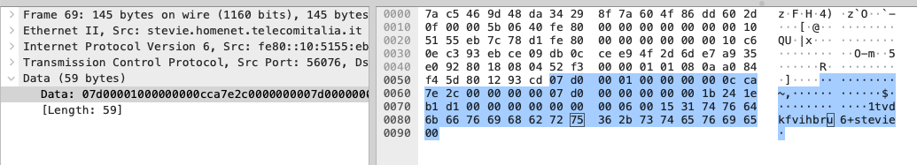
Using lsof confirmed that this was indeed the communication between the client phone and Logic listening on port 56076:

Initially I tought this was just some Logic Pro specific protocol and very lazily started looking into it, without much success mostly due to lack of motivation given the very limited scope of the research. After a while I tweeted asking if anyone had ever seen anything like it. @isComputerOn pointed out that this looked a lot like a protocol that has been partially reversed and presented by Alban Diquet back in 2014. Unfortunately, however brilliant, this research covers the protocol at a very high level and doesn’t really document the packets, their fields and how to establish a connection from anything but a client using the Apple framework. However, this helped me a lot in two ways: first it helped me realize this was not just Logic Pro specific, but that it was part of the Multipeer Connectivity Framework, and gave me a few hints about the general logic of the protocol itself.
With renewed curiosity and motivation then I jumped into this rabbit hole and managed to reverse engineer all network packets. This allowed me to write a Python proof of concept client that automatically discovers any MPC servers, initializes the connection and succesfully exchanges application specific data packets.
Moreover, while sending crafted packets and attempting all sorts of things, I’ve discovered several vulnerabilities in the Apple custom made parsers. I will not discuss them here (exception made for the session spoofing) but at the same time I’m not interested in reporting them to Apple, I’ve heard way too many negative stories about their disclosure program and in general how they mistreat researchers.
Let’s see how this whole thing works! :)
MultipeerConnectivity Framework
Apple’s documentation describes the framework like so:
The Multipeer Connectivity framework supports the discovery of services provided by nearby devices and supports communicating with those services through message-based data, streaming data, and resources (such as files). In iOS, the framework uses infrastructure Wi-Fi networks, peer-to-peer Wi-Fi, and Bluetooth personal area networks for the underlying transport. In macOS and tvOS, it uses infrastructure Wi-Fi, peer-to-peer Wi-Fi, and Ethernet.
The document mostly describes how they abstracted the protocol in several classes while being extremely vague about how the thing actually works at the packet level. In reality they mostly reused existing protocols such as MDNS and a customized STUN implementation (in Logic Pro specific case, this doesn’t always apply to apps using this framework), plus a custom TCP based protocol for which they heavily relied on custom (and extremely badly) written parsers.
Discovery Phase: Multicast DNS
The very first thing that I’ve noticed was that, despite the server port being randomized at each application startup, the client application never asked me for the server ip address nor tcp port. This was a strong indicator that something else was happening on the network before the TCP session was being established, as if the server (and possibly the client as well) broadcasted this information in such a way to be automatically discoverable, as also hinted by the wording used in the documentation.
My informed guess was multicast DNS as I’ve seen this protocol being (ab)used a lot from Apple (Bonjour for instance), and Wireshark confirmed my guess. Both the server and the client are broadcasting their hostnames and peer identifiers (more on this later) on the network so that they can find each other without user interaction.
Here’s how the server advertisement looks like on Spycast:
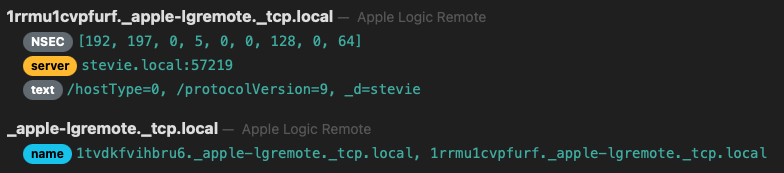
We can see which TCP port is being used (57219), some application specific information in the text record and a weird string “1tvdkfvihbru6”, the PeerID.
At the same time, the client is broadcasting some information such as its hostname:
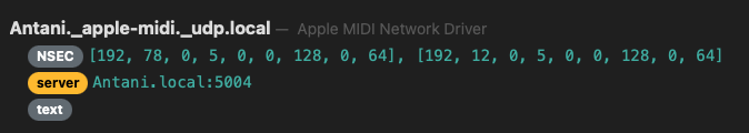
Keep in mind that all this data is visible by anyone on the same network, this is an important detail as we’ll see shortly when I’ll describe how the spoofing works.
How a PeerID is made
Before proceeding to the next part, let’s stop for a moment to see how a peer is identified in this protocol and what that “1tvdkfvihbru6” string is.
Upon startup, each peer is represented by a MCPeerID object. Long story short, a random 64bit integer is generated and converted to base36.
So that 1tvdkfvihbru6 in base36 is 8670129607084362000 in base 10. This number is used to uniquely identify the host during the session, regardless of the hostname itself and it’s present in various forms in most of the packets we’re about to see.
Handshake Phase: Hellos and Acks
After the client discovers the server peer via MDNS the connection is initiated to the TCP port indicated in the advertisement. This is when things started being complicated as the protocol is entirely custom and undocumented.
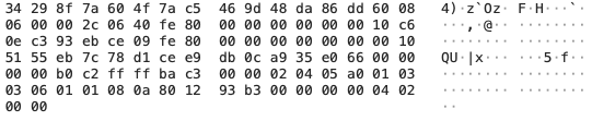
I needed to work my way from something like this:
To something like this.
For this task I’ve performed dozens of tests such as:
- See if similar packets all started with the same signature bytes (they did).
- See if by changing the hostname of the client, some other fields (possibly string length fields) changed reflecting the new length (they did).
- See if there was any checksum going on by looking at 2 bytes and 4 bytes words that changed depending on the contents (there are).
- See if packets were encapsulated with a common header plus a packet-specific payload, which length should be indicated in the header (it is).
After a few days of testing I’ve managed to understand that all the packets started with a header that looks like this:
- The first 2 bytes are the packet signature and determine the packet type (Hello, Ack, Invite, …).
- The next 4 bytes are a sequence number plus flags that are used only for some specific payloads.
- We then have 2 bytes indicating the payload size after the header.
- Following 4 bytes are the CRC32 of the whole packet (i wasn’t sure which checksum was, so I bruteforced it :D)
- The last 4 bytes of the header are unknown to me but they always seem to contain the same value.
With this new knowledge I started looking into the payload of the first packets and identified how the connection handshake works:
- The client sends an Hello packet made of the header and its PeerID.
- The server responds with an Ack packet, made of just the header and no payload.
- The server then sends its own Hello packet containing its PeerID (which seems redundant given its already broadcasted via MDNS, but whatever …).
- The client sends an Ack to the server Hello.
- Finally the client sends an Accept packet also only made of the header and no payload, indicating that the first part of the handshake is complete. The reason why the client is responsible for this and not the server will always remain a mystery to me :D
You can find the implementation of this handshake process here.
Authorization Phase: Spoofable Invites and BPlist inside BPlist inside TCP
After this mutual introduction, the client will send an Invitation packet and this is where things start getting covoluted (a la Apple): as we can see from the next picture, the Invite packet is made of the header plus a Binary Property List as indicated by the “bplist00” signature visible in cleartext in the packet:
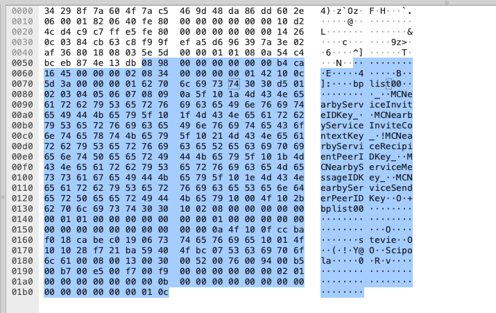
A BPlist is basically a binary encoded XML document, in this case containing the following fields:
- MCNearbyServiceInviteContextKey: a bplist encoded (yes it’s a bplist inside a bplist …) integer, always 0x2.
- MCNearbyServiceInviteIDKey: an integer always set to 0x0.
- MCNearbyServiceMessageIDKey: an integer message identifier, always 0x1 for invites.
- MCNearbyServiceRecipientPeerIDKey: the message recipient (the server in this case) PeerID, encoded as described next.
- MCNearbyServiceSenderPeerIDKey: the message sender (the client) PeerID.
In the last two fields, the peer identifiers are encoded as:
- 8 bytes containing the numeric peer identifier, big endian.
- 1 byte containing the peer hostname length.
- N bytes containing the unicode peer hostname.
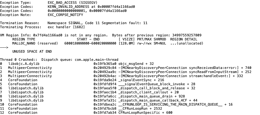
The server responds with an Ack and at this point two things can happen: if the client is unknown to the server, a prompt will be shown in order to let the user decide wether to authorize it or not:
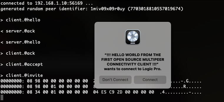
However, if the client has been previously authorized, no prompt will be shown and the communication will silently continue to the next data exchange step.
At this point you might ask, how does the server store this authorization information? Is it some sort of session cookie? A more advanced cryptographic challenge mechanism? Black magic? Well my friends, often reality is way duller and dumber than what you might imagine :D
They just don’t give a damn and keep a “string peer_hostname -> bool authorized” association … yes, you read that right, client authorization only relies on the (spoofable) client hostname, they don’t even care about the peer identifier number.
Remember how all this information (and more) is being broadcasted in cleartext via MDNS for everyone to enjoy? Yep that’s right, an attacker can wait for a legit client to be authorized and then use its hostname (not on the network, just in the MCNearbyServiceSenderPeerIDKey field) in order to either hijack the legit session, or just create a new one of its own and completely bypass the authorization prompt.

Anyways … if authorized, the server will conclude this phase by sending an InviteResponse, which is identical to the client Invite packet, back to the client. You can find the client invite logic here and the wait loop for the server response here.
Let’s continue.
Data Exchange Phase
After the server accepted the invite, the client will proceed by sending a ClientData packet, another bplist encoded payload containing the following fields:
- MCNearbyServiceInviteIDKey: the invite key received with the server InviteResponse.
- MCNearbyServiceMessageIDKey: an incremental integer being InviteResponse.MCNearbyServiceMessageIDKey + 1.
- MCNearbyServiceRecipientPeerIDKey: client peer id encoded as previously described.
- MCNearbyServiceSenderPeerIDKey: server peer id encoded as previously described.
- MCNearbyServiceConnectionDataKey: connection data as bplist (again, a bplist inside a bplist …), described next.
The interesting part here is the MCNearbyServiceConnectionDataKey field, which contains a bplist encoded binary payload made of:
- A header composed of:
- 1 signature byte (0x80).
- 1 byte bitmask of security flags indicating if encryption is enabled (not in this case, LOL).
- 2 bytes indicating the total size of the payload.
- 1 byte indicating the number of segments / entries in the payload.
- A list of IPv4 and IPv6 addresses, one for each network interface of both peers.
- A variable number of segments describing each network interface of both peers, made of:
- 1 signature byte (0x61).
- 4 bytes of the numeric peer id (either the client or the server one) trimmed down to 32bits.
- 4 bytes of a random identifier, my guess is that this creates a new unique identifier together with the previous field.
- 1 byte indicating the interface type ( ipv4=0x5A ipv6=0x0A ).
- 3 bytes of padding.
- 1 byte containing the interface IP index bit-masked with its type.
- 2 bytes containing an UDP port.
Since the application specific part of the protocol works on UDP, by exchanging this data both endpoints become aware of on which possible IP and UDP ports the next part of the communication can happen.
STUN a la Facetime
After the previous step, an Apple custom implementation of STUN is used to determine NAT type and which IP:PORT pair is best suited for the communication. Interestingly, while digging hard into this rabbit hole and reversing other frameworks that were referenced here and there, I found out this is the same exact mechanism that Apple Facetime also uses.
I’ve implemented a very basic STUN processor here, what happens is:
- The server will pick one of the IP:UDP_PORT pairs sent in the ClientData and sends a STUN Binding Request containing these STUN attributes:
- USERNAME: containing the server and client integer peer identifiers.
- ADDRESS_ERROR_CODE: always 0x6.
- ALTERNATE_DOMAIN: always 0x03f2.
- APPLE_NTP_DELAY: you would see this labled as ICMP by Wireshark, however Apple is using this specific attribute identifier to indicate the NTP delay, as I found out by Ghidra-ing the s*it out of it :D
- ICE_CONTROLLING: randomly generate STUN tie breaker / session id.
- The client will respond with its own Binding Request, replacing ICE_CONTROLLING with ICE_CONTROLLED and its tie breaker.
- The server will send a Binding Response with a MAPPED-ADDRESS attribute indicating the final IP:UDP_PORT pair for the communication.
- The client will send its own Binding Response with its UDP MAPPED-ADDRESS.
From this point on, an UDP connection is established between the two MAPPED-ADDRESSes and application specific data is exchanged.
Brief note on OSPF
Despite the Logic Pro specific protocol happening after all these steps is out of the scope of this post, I want to briefly mention how it works.
Interestingly, this protocol is referenced as OSPF from the framework:
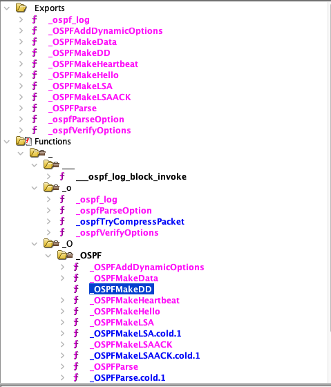
Howver it has almost nothing in common with the Open Shortest Path First protocol. Despite some of these function names reference valid OSPF messages such as LSA, LSAACK and so on, the Apple implementation is entirely different.
You can find a partial python implementation here that will be used after the previous step in order to correctly start the “OSPF” session and start receiving data from the server.
In this case, each packet is made of this header:
- 1 byte of protocol type signature (0xc1).
- 1 byte of packet type signature.
- 2 bytes of packet size.
- 2 bytes indicating OSPF channel, mostly unused.
- 2 bytes with the packet CRC16/ARC checksum (again, bruteforcing the type of checksum helped a lot).
- 4 bytes of the sender peer id.
- 4 bytes of the receiver peer id.
Following, the packet specific payload.
You can find the definitions of some of the Logic Pro packets here and the OSPF server code that will initialize the session and start getting server updates here.
Conclusion
This has definitely been a fun ride during which I’ve learned a lot of new stuff about how Apple frameworks handle network communications. I want to reiterate my gratitude to Alban Diquet for his research and to @isComputerOn for pointing me to the right direction when I was about to give up on what it seemed something entirely irrelevant, thanks you so much guys! <3
I also want to comment on something i’ve heard during a talk presented at the last 0x41 conference.
The researcher who was presenting and who specialized in fuzzing Apple products, mentioned how at the beginning of his path, someone who’s highly respected and recognized in the infosec community and industry, told him that “fuzzing Apple’s network protocols was a dumb idea”, which unfortunately convinced the researcher to look elsewhere.
Well, my highly respected and recognized dude, I can tell you it is not a dumb idea, at all, there’s a lot of unexplored attack surface there. What was dumb, very close-minded and ignorant, is your take about it.
Anyways … you can find the project on my github as usual, enjoy!